 A+D Technical Planning Guide
Architecture + Design Technical Planning Guide
Self-serve beverage system planning for hospitality projects — Beverage Walls and Tekerator mobile stations.
| Document no. | PTK-AD-001 | Revision | 1 — Verified specs |
| Issue date | 2026-09-02 | Status | FOR COORDINATION |
Architects, interior designers, MEP engineers, foodservice consultants, millworkers, general contractors, developers and hospitality project teams.
Pourtek Beverage Wall and Tekerator one-sheets and the Pourtek Installation Guide REV 06/26. Values not stated in those sources are marked for issue per project.
This guide carries no engineering stamp. Project-specific dimensions are issued in writing by Pourtek's design team against the project submittal (Section 15) and supersede the schematics here. Consult local regulations and licensing before dispensing any alcoholic beverages.
Contents
- 01Cover + document control
- 02System overview
- 03Configuration standard
- 04Beverage Wall planning
— not in project scope - 05Tekerator planning
— not in project scope - 06Required clearances
- 07Electrical
- 08Data + network
- 09Draft system + refrigeration
- 10Plumbing, drainage + line cleaning
- 11Back-of-house + electronics housing
- 12Rough-in matrix
- 13Trade responsibility
- 14Installation sequence
- 15Design submittal checklist
- 16CAD / BIM files
- 17Project-specific design support
System overview
Pourtek is a self-serve, RFID-activated beverage dispensing system. Guests tap a card, wristband or keychain at a landscape touchscreen, pour from the faucets served by that screen, and are charged by the ounce — metered to a tenth of an ounce. Pricing, inventory and pour data live in a Salesforce-powered cloud platform; there is no on-premise server. The components below are the ones a project team coordinates.
| Component | Function | Coordination |
|---|---|---|
| Beverage Wall | Fixed, built-in run of faucets and guest screens along a bar or venue wall — 2 to 60+ faucets. | Needs a false wall with blocking, back-of-house draft delivery, and power and data at the wall. Sections 04 and 12. |
| Tekerator | Portable, all-in-one dispensing station with integral refrigeration; 2-, 4- or 6-faucet configurations. No construction. | Needs a floor position, a dedicated 120 V / 15 A outlet, network coverage and a keg-change route. Section 05. |
| Guest screens | Landscape touchscreens with integrated RFID/NFC readers, venue-branded. 10.1″ serves 1–2 faucets; 15.6″ serves 3–4. Powered over Ethernet, no batteries. | Screen size sets the module width (Section 03). Each screen mounts directly above the faucets it controls. |
| Pour-control assemblies | Solenoid valve and flow meter on every line, with FOB foam detection. Meters to 0.1 oz. | Mounted behind the wall close to the point of dispense, in a dry, ventilated housing. Section 11. |
| Controllers + edge router | Pre-configured network kit. The edge router provides internet and/or cellular failover. | Located in the electronics housing on the dedicated system circuit. Sections 07 and 08. |
| Handheld system managers | Android handhelds with NFC and barcode ID scanning for check-in, tabs, keg changes and reports. No desktop check-in station. | Require facility-wide Wi-Fi and a secure overnight charging spot. |
| RFID credentials | 500 venue-branded NFC cards ship with each system; wristbands and keychains available; hotel keycard compatible. | Card issuance point — host stand, bar or front desk — is a project design input. |
| Cloud platform | Real-time analytics, inventory, pricing, pour limits and multi-location management from one login. POS integrations: GoTab, Clover, Roller, Parafait. | Needs 300+ Mbps internet at the venue. Section 08. |
- Guest screens with RFID/NFC readers
- Pour-control assemblies (valve + flow meter per line)
- Controllers, PoE switch and edge router
- Handheld system managers
- 500 branded RFID cards per system
- Cloud platform and POS integration
- Installer/trainer on site
- Draft lines, glycol systems, towers and faucets — certified draft installer
- Walk-in cooler and refrigeration — refrigeration company
- CO₂ / nitrogen and kegs — gas supplier and distributors
- Line-cleaning equipment and chemicals
- Power, Cat6 cabling, Wi-Fi and internet service
- False wall, blocking, millwork and finishes
Configuration standard
The screen-plus-faucet group is the planning module. Two module types are available and may be combined along one wall. Choose the module type early: it sets faucet pitch, the wall length to reserve, screen count and the number of pour-control assemblies.
| Faucets | Module A · pairs at 12″ o.c. | Module B · quads at 18″ o.c. | Screens A / B |
|---|---|---|---|
| 8 | 4′-0″ | 3′-0″ | 4 / 2 |
| 12 | 6′-0″ | 4′-6″ | 6 / 3 |
| 20 | 10′-0″ | 7′-6″ | 10 / 5 |
| 40 | 20′-0″ | 15′-0″ | 20 / 10 |
| 60 | 30′-0″ | 22′-6″ | 30 / 15 |
Length = module pitch × module count. Add at least 4″ from the outermost faucet to each side wall (Installation Guide), plus any millwork returns. The final faucet layout is set on the Pourtek shop drawings. Renderings that show five or more faucets under one screen, a screen detached from its faucets, or a portrait screen do not represent a Pourtek configuration and must be corrected before issue.
Beverage Wall planning
Drawings on this sheet are schematic and dimension-neutral. Verified values are stated; lettered dimensions are issued per project by Pourtek's design team, which works with you or your architect to lay out the wall. Nothing here is drawn to scale.
| Key | Dimension | Value | Source |
|---|---|---|---|
| 12″ | Module pitch, 10.1″ screen over a faucet pair | 12″ o.c. recommended | Beverage Wall one-sheet |
| 18″ | Module pitch, 15.6″ screen over 3 or 4 faucets | 18″ o.c. recommended | Beverage Wall one-sheet |
| ≥4″ | Outermost faucet to side wall | 4″ minimum | Installation Guide |
| A | Overall wall length | PER PROJECT — rule of thumb, Section 03 | Pourtek shop drawings |
| B | Screen centreline above finished floor | PER PROJECT | Pourtek shop drawings |
| C | Faucet centreline above finished floor | PER PROJECT — set with the draft installer | Draft design |
| D | Clearance from the tallest tap handle to the screen bracket | Required — plan for nitro handles | Installation Guide |
| Key | Dimension | Value | Source |
|---|---|---|---|
| F | Guest operating and queue zone depth | PROJECT INPUT · PER CODE | Project team · AHJ |
| G | Cooler and service zone depth | Cooler sizing, Section 09 | Installation Guide · draft design |
| H | False-wall cavity for shanks, assemblies, lines and electronics housing | PER PROJECT | Pourtek · draft installer |
| J | Drip tray / counter projection from the finished wall | PER PROJECT | Millwork · draft installer |
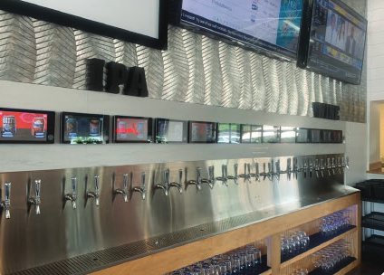
- Screens mount above and between the faucets they control; keep soffits, TVs and signage clear of the screen line.
- Module A and Module B may be mixed on one wall; keep each screen over its own faucets.
- Provide blocking for screen brackets, shanks and assemblies; extents on the Pourtek shop drawings.
- Reserve a dry, ventilated electronics housing in the false wall above the backsplash — Section 11.
- Direct draw keeps the cooler behind the wall; long draw runs a glycol trunk line — Section 09.
Tekerator planning
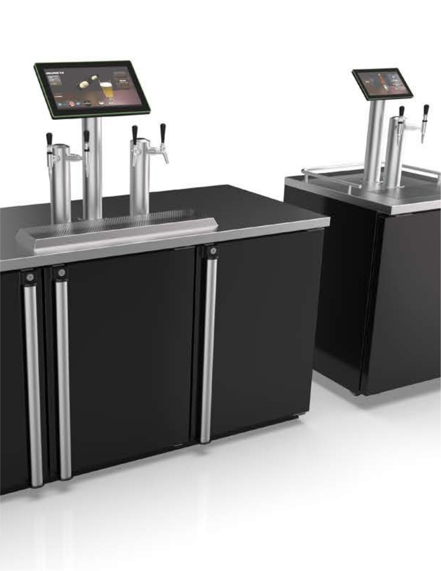
The Tekerator is a portable, stand-alone dispensing station with refrigeration, CO₂ regulator and couplers built in. It needs no construction: reserve a floor position, a dedicated outlet, network coverage and a keg-change route. It follows the same screen-to-faucet rule — 2-faucet units carry a 10″ screen, 4-faucet units a 15.6″ screen.
| Model data | Verified value |
|---|---|
| 4-faucet | 80″W × 29″D × 50″H to top of screen · 15.6″ screen |
| 2-faucet | 25″W × 30″D × 50″H to top of screen · 10″ screen |
| Configurations | 2, 4 or 6 faucets |
| Finish | Stainless steel, matte, or custom branded wrap (ships pre-applied) |
| Mobility | Casters included; replaceable with legs for fixed installs |
| Gas kit | CO₂ regulator and couplers included; optional nitrogen kit for red wines |
| Source | Tekerator one-sheet · Installation Guide REV 06/26 |
| Item | Requirement | Coordination |
|---|---|---|
| Power | Dedicated 120 VAC / 60 Hz / 1-phase, 15 A circuit at each intended unit position. Tekerator one-sheet | Standard receptacle; surge protection recommended. |
| Network | Reliable high-speed internet; wireless and cellular options where wired service is unavailable. Tekerator one-sheet | Confirm Wi-Fi at every intended position, including patios and event spaces. |
| Gas | CO₂, nitrogen or both from your gas provider, depending on the beverage mix. Tekerator one-sheet | Cylinder location and securing per code. |
| Service | Keg loading and coupling by on-site staff; cleaning per board-of-health or industry standard, whichever is more frequent. Tekerator one-sheet | Confirm door swing and service side before placing a unit against a wall. |
| Ventilation | Integral refrigeration rejects heat at the unit. Clearance for enclosed or built-in positions: PER PROJECT | Confirm with Pourtek before recessing a unit into millwork. |
| Delivery | Crated; someone must accept delivery; advise at ordering whether a lift-gate is required. Tekerator one-sheet | Check doors, elevators and corridors against 80″ × 29″ or 25″ × 30″ on casters. |
| Lead time | 6 to 8 weeks depending on location. Installer/trainer arrives on delivery or soon after; same-day install and training. Tekerator one-sheet | Your IT support and draft-service contractor on site on training day. |
Required clearances
Clearances govern the space the design team reserves around the equipment. Accessibility clearances are additionally governed by the applicable code and the authority having jurisdiction; Pourtek values never reduce a code minimum.
| Clearance | Purpose | Requirement | Source |
|---|---|---|---|
| Outermost faucet to side wall | Working room at the end faucets and millwork returns. | ≥4″ | Installation Guide |
| Between faucet groups | Guest elbow room; screen bezel spacing. | 12″ o.c. pairs 18″ o.c. 3/4 groups | Beverage Wall one-sheet |
| Above the tallest tap handle | Screen-bracket clearance; plan for nitro handles. | REQUIRED · PER PROJECT | Installation Guide |
| Front operating zone | A guest taps, holds a glass under the faucet and steps away. | PROJECT INPUT · PER CODE | Project team · AHJ |
| Queue and standing zone | Peak-traffic circulation behind the operating zone. | PROJECT INPUT | Project team |
| Accessible approach and reach | Clear floor space and reach range to the reader, screen and faucet handle. | PER CODE / AHJ · HEIGHTS PER PROJECT | Code · Pourtek |
| Check-in station | Not required — the system is managed on handhelds. | None — secure overnight charging spot only | Installation Guide |
| Rear service access | Reach to pour-control assemblies, controllers and shanks. | Removable front or access panels; extent per project | Installation Guide · Pourtek |
| Cooler doors and keg-change route | Roll, lift and couple a full keg; keg stackers on larger coolers. | PER COOLER DESIGN | Refrigeration · draft installer |
| Tekerator service side | Keg-loading door swing and heat rejection from integral refrigeration. | PER PROJECT | Pourtek |
Electrical
Pourtek screens and controllers run on standard Power over Ethernet and contain no batteries, so no receptacles are needed at the screens. Power is concentrated at the electronics housing. Circuit sizing, GFCI protection and disconnects are determined by the project electrical engineer against this schedule and applicable code.
| Equipment | Circuit | Furnished by | Notes |
|---|---|---|---|
| Beverage Wall — system electronics (switch, modem, edge router, controllers) | 1 × dedicated 120 VAC, 1-phase, 15 A | Electrical contractor | At the electronics housing. Surge protection recommended. Source: Beverage Wall one-sheet. |
| Beverage Wall — pour-control assemblies | +1 × 15 A or 20 A circuit per 10 faucets | Electrical contractor | Example: 20 faucets → two additional circuits. Source: Beverage Wall one-sheet. |
| Guest screens | Power over Ethernet | Pourtek switch · low-voltage cabling | No batteries, no receptacles at the screens. Source: Beverage Wall one-sheet. |
| Tekerator | 1 × dedicated 120 VAC / 60 Hz / 1-phase, 15 A per unit | Electrical contractor | Standard receptacle at each intended position. Source: Tekerator one-sheet. |
| Walk-in cooler · glycol power pack | PER EQUIPMENT SELECTED | Refrigeration company · electrical contractor | Not Pourtek-supplied. Coordinate with the draft design, Section 09. |
| Handheld charging | Convenience receptacle | Electrical contractor | At the secure overnight charging spot. Source: Installation Guide. |
Data + network
The platform is cloud-hosted: no on-premise server, no server closet, no nightly backups, and updates push remotely. Professional networking must be installed, tested and certified before Pourtek's install date.
| Item | Requirement | Coordination |
|---|---|---|
| Internet | 300+ Mbps reliable service. The Pourtek edge router provides internet and/or cellular failover. Installation Guide · Beverage Wall one-sheet | Owner / IT provides service; in-service date precedes commissioning. |
| Wired drops | Cat6 home-run to each wall and each fixed unit — terminated, tested, certified and labeled. Installation Guide | Low-voltage contractor, before wall close-in (Section 12). Terminates in the electronics housing. |
| Wi-Fi | Facility-wide coverage. Handhelds operate over Wi-Fi; Tekerators may connect wirelessly. Installation Guide · Tekerator one-sheet | Survey coverage at the wall, every Tekerator position and the full service area. |
| IP, VLAN and firewall | Network requirements are issued by Pourtek to owner IT at the kickoff call. PER PROJECT | Segregation from guest Wi-Fi and outbound rules agreed with IT before configuration. |
| POS | Integrations: GoTab, Clover, Roller, Parafait. Charges post to the guest's tab. Installation Guide | Three-way coordination: Pourtek · POS provider · owner IT. POS platform is a submittal item (Section 15). |
| Cloud and data | Salesforce-powered pour and inventory data; AWS-hosted configuration. Installation Guide | No server-room allocation for Pourtek equipment. |
| Internet outage | Contact support for the offline procedure; pours sync when service returns. Installation Guide | Include in staff training; cellular failover reduces exposure. |
Draft system + refrigeration
Pourtek meters and controls the pour. The draft system that delivers product to the faucet — lines, towers, faucets, cooling and gas — is designed and installed by a certified draft installer and refrigeration company. The beverage program drives it: beer, wine, cider, cold-brew, kombucha and mixed drinks call for different temperatures, gases and line materials.
Cooler directly behind the wall; faucets on the false wall; short lines. Electronics housing sits in the false wall above the backsplash. Typical where the cooler can back onto the wall.
Glycol-cooled trunk line from a remote cooler; required for multi-floor runs. One keg can feed multiple taps across floors. Needs a glycol power-pack location, an insulated trunk-line path and a service cabinet with a removable front for electronics.
| Faucets | Walk-in | Note |
|---|---|---|
| 12 | 6′ × 8′ | |
| 20 | 10′ × 8′ | |
| 40 | 18′ × 8′ | Keg stackers recommended |
| 70+ | ~110 kegs | Sized with the draft installer |
Source: Installation Guide REV 06/26. Final size follows keg count and change-out frequency.
FOB detectors stop foam from being poured or billed. Pour-control assemblies mount close to the point of dispense, in flow direction — reversed installs will not meter — with beverage lines in contact with the glycol lines.
Source: Installation Guide REV 06/26.
| Item | Requirement | Coordination |
|---|---|---|
| CO₂ | Standard for beer and carbonated products; supplied by your gas provider. | Cylinder storage, securing, ventilation and gas detection per code. |
| Nitrogen / blended gas | Red wines, nitro coffee and some kombucha. Optional nitrogen kit on Tekerators. | Only where the beverage program requires; storage adjacent to CO₂. |
| Kegs | Sized to the program and change-out frequency; one keg can serve several faucets. | Delivery route from receiving to the cooler is a project layout item. |
| Line routing | Continuous accessible path — chase, ceiling or trench — with penetrations, fire-stopping and cleaning access. | GC provides the chase; the draft installer runs and balances the lines. |
| Not in Pourtek's box | Draft lines, glycol systems, towers and faucets, walk-in cooler, gas, kegs, line-cleaning equipment. | Via the certified draft installer and suppliers. Source: Installation Guide. |
Plumbing, drainage + line cleaning
Pourtek equipment has no water or drain connection. Drainage requirements come from the drip trays, the cooler and any glycol equipment, and are set by the draft design and the authority having jurisdiction.
| Item | Purpose | Requirement |
|---|---|---|
| Drip trays | Waste from pours and cleaning along the faucet run. | Drained or undrained per the draft design; indirect waste to a floor sink where the AHJ requires. PER CODE / AHJ |
| Floor sink | Receptor for indirect waste behind or beneath the wall. | Location coordinated with the cooler and the line chase before slab or floor finish. PER CODE / AHJ |
| Condensate | From the cooler evaporator and any glycol power pack. | Per the refrigeration equipment selected by the project. |
| Water | Rinse or cleaning supply at the wall, if desired. | Project decision — not required by Pourtek equipment. PROJECT INPUT |
| Line cleaning | Draft lines cleaned per board-of-health or industry standard, whichever is more frequent. | Venue staff or draft-service contractor; equipment and chemicals venue-supplied; keep couplers and faucets accessible. Tekerator one-sheet · Installation Guide |
Back-of-house + electronics housing
The diagram shows what connects to what. It is a relationship diagram, not a physical arrangement — adjacency, distance and routing are set per project.
- Dry and ventilated.
- Direct draw: in the false wall above the backsplash.
- Long draw: a service cabinet with a removable front.
- Houses the switch, modem, edge router and controllers on the dedicated 15 A circuit.
- The Cat6 home-run terminates here.
- Pour-control assemblies nearby, close to the point of dispense.
Source: Installation Guide REV 06/26.
- No check-in station — plan a secure overnight charging spot for the handhelds with a convenience receptacle.
- Decide where credentials are issued: host stand, bar or front desk. Hotel keycards can serve as pour credentials where integrated.
- Keep the keg-change route from receiving to the cooler clear of the guest zone.
Rough-in matrix
Everything below must be in place — and, for network, certified — before Pourtek's technician arrives. Locations are fixed on the Pourtek shop drawings.
| Item | Rough-in | By whom | When |
|---|---|---|---|
| Electrical | Dedicated 15 A system circuit plus one 15/20 A circuit per 10 faucets at the electronics housing; 15 A receptacle at each Tekerator position; convenience receptacle at the charging spot. | Electrical contractor | Before wall close-in |
| Data | Cat6 home-run to each wall and fixed unit — terminated, tested, certified, labeled; facility-wide Wi-Fi. | Low-voltage contractor · owner IT | Before close-in; certified before the install date |
| Blocking | Backing for screen brackets, towers and shanks, pour-control assemblies and access panels. | GC | Framing — extents per shop drawings |
| False wall / chase | Cavity for shanks, assemblies, lines and the electronics housing; removable front for long draw. | GC · millworker | Before equipment install |
| Beverage lines | Trunk-line path, sleeves, penetrations and fire-stopping between cooler and wall. | GC (chase) · draft installer (lines) | Before wall close-in |
| Cooler | Walk-in cooler, refrigeration and glycol power pack per Section 09. | Refrigeration company | Stage 2 of the build (Section 14) |
| Gas | Cylinder location and securing; gas line to the draft equipment. | Gas supplier · draft installer | Before draft install |
| Drainage | Floor sink and indirect waste per Section 10. | Plumbing contractor | Before slab or floor finish |
| Finish wall + millwork | Cleanable finish; cut-outs per approved shop drawings; drip-tray and counter support; access panels. | GC · millworker | Before Pourtek install |
| Internet service | Live 300+ Mbps service at the demarc. | Owner / IT | Before commissioning |
Trade responsibility
Pourtek's Project Manager is the single point of contact from order confirmation to go-live. Responsibilities below follow the Installation Guide; nothing here overrides a signed Pourtek quote or scope of work.
| Scope | Responsible | Coordinates with |
|---|---|---|
| Wall layout, module configuration, shop drawings | Pourtek design team | Architect · GC · draft installer |
| Screens, pour-control assemblies, controllers, router, handhelds, credentials | Pourtek | — |
| Draft design; lines, towers, faucets, glycol | Certified draft installer | Pourtek (assembly placement) · architect |
| Walk-in cooler and refrigeration | Refrigeration company | Draft installer · GC · electrical |
| Beverage gas and kegs | Gas supplier · distributors | Draft installer |
| Floor plan, elevations, finishes, code compliance | Architect | Pourtek design team |
| Framing, blocking, false wall, penetrations | General contractor | Pourtek shop drawings · millworker |
| Millwork, drip-tray support, access panels | Millworker | GC · draft installer |
| Power circuits and receptacles | Electrical contractor | Project electrical engineer |
| Cat6 drops, Wi-Fi, internet, VLAN and firewall | Low-voltage contractor · owner IT | Pourtek (network requirements) |
| Drainage and floor sinks | Plumbing contractor | AHJ · draft installer |
| POS integration | Pourtek · POS provider | Owner IT |
| Installation, configuration, testing, training | Pourtek installer/trainer | Owner IT and draft contractor on site |
| Line cleaning and ongoing draft service | Venue · draft-service contractor | Board-of-health standards |
Installation sequence
- 01Draft system designCertified draft installer designs lines, cooling and gas from the approved beverage program and the Pourtek wall layout.
- 02Walk-in cooler installRefrigeration company; sized per Section 09.
- 03Tap wall build-outFraming, blocking, false wall and rough-ins per Section 12.
- 04Draft system installLines, towers, faucets and glycol set; gas connected and leak-tested.
- 05Screen mount installBrackets set to the Pourtek shop drawings, clear of the tallest tap handle.
- 06Final drillingCut-outs and penetrations finished against the installed hardware.
- 07Pourtek system install + setupScreens, assemblies, controllers and network; 1–3 days on site including testing and training. Your IT support and draft contractor available.
- Kickoff call with the Pourtek Project Manager after order confirmation.
- Beverage Wall: at least 8 weeks from order to delivery and install prep; align delivery to the build.
- Tekerator: 6–8 weeks to crate delivery, then same-day install — position, connect gas, load kegs, join the network, pour-test, train.
- Install-day training: check-in, ID verification, credential pairing, keg changes, line cleaning.
- Remote onboarding: dashboards, pricing, promotions, pour limits, reporting.
- 24/7 support with remote diagnostics and proactive monitoring under the ongoing support agreement.
Design submittal checklist
Pourtek's design team issues project-specific dimensions and requirements against this set. The first seven items are what the venue brings to the kickoff call; incomplete submittals return with the missing items marked.
| Item | What Pourtek needs from it | Format | |
|---|---|---|---|
| Floor plan | Wall location, adjacencies, cooler position, receiving route, Tekerator positions. | PDF · DWG | |
| Contacts | Owner, architect, GC, low-voltage electrician, draft installer, refrigeration company, gas supplier, IT. | List | |
| Logo and brand files | Screen branding, RFID cards and any Tekerator wrap. | Vector files | |
| POS details | Platform, version and integration contact. | Name | |
| Network details | ISP and bandwidth, Wi-Fi coverage, IT contact, security policy. | Narrative | |
| Location and shipping details | Delivery address, receiving hours, lift-gate requirement. | Text | |
| Go-live date | Target opening and construction milestones. | Date | |
| Tap-wall elevation | Wall extent, ceiling and soffit heights, adjacent openings, TVs and signage above the screen line. | PDF · DWG | |
| Faucet count and module type | 10.1″ pairs, 15.6″ groups or a mix; Tekerator count and configuration (Section 03). | Number · selection | |
| Beverage mix | Beer, wine, cider, cocktail and non-alcoholic split; target products; nitro items. | List | |
| Refrigeration strategy | Direct draw or long draw; existing cooler if any; distance from cooler to wall. | Selection · plan mark-up | |
| Venue capacity and peak traffic | Occupant load; guests per hour at peak; event versus daily pattern. | Number · narrative | |
| Electrical information | Service, panel location and spare capacity. | Panel schedule | |
| Finish concept | Wall finish, millwork intent, drip-tray and counter design. | Images · narrative |
CAD / BIM files
Dimensioned project drawings — plan, elevation, section, cut-outs and blocking extents — are issued by Pourtek's design team against the submittal in Section 15 and supersede the schematics in this guide.
| Format | Availability | Intended use |
|---|---|---|
| PDF details | PER PROJECT | Dimensioned shop drawings for the GC, millworker and draft installer. |
| DWG | ON REQUEST — CONFIRM WITH POURTEK | 2D plan and elevation blocks for the wall and Tekerator footprints. |
| Revit | ON REQUEST — CONFIRM WITH POURTEK | Families for BIM coordination and clash detection. |
No native file is represented as existing until your Pourtek Project Manager confirms it in writing. Files issued for a project supersede the dimension-neutral drawings in this guide.
Need project-specific design support?
Pourtek's design team works with you or your architect to plan the beverage-wall space while maximizing efficiency and scarce floor space. Send your plans and preliminary beverage program for configuration review.
Include the Section 15 checklist. Pourtek returns lettered dimensions and confirmed requirements against your submittal. Consult local regulations and licensing before dispensing any alcoholic beverages.